Outreach Project
- Home
- Arduino Rover & 3D Printing
UNITE: Army Educational Outreach: Introduction to Mechatronic at Jackson State University
There is significant interest in STEM and STEM-related teaching, learning, and career opportunities. Science, technology, engineering, and mathematics are fundamental to the technological field called mechatronics. Mechatronics integrates engineering principles and methods with the fields of mechanical and electrical engineering and computer programming in prototype designs of technical products that used in our daily live.
The Jackson State University UNITE 3D Printing and Rover design project is directed toward the explorations with a 3D printer, electronic controls, computer programming to print, assemble, and program a Robot Rover to be operated in autonomous and remote control operations.
The followings are detail descriptions of CAD designs, 3D printing mechanical parts, assembling & connecting electronic components, and programming an Arduino microcontroller development board. Special skills gained include understanding the 3D design and printing processes, working with electrical and electronic circuits, developing C+ like programming skills. The purposes of the workshop were directed toward activities that would enhance STEM educational endeavors and provide insights and awareness of engineering and related careers.
3D Production Files for Rover
The Rover chassis platform provides all mounting holes and cutouts to support the Arduino circuit board, servo, and power switch. The battery holder is attached with double-sided tape. It is important to note that with relatively larger surface areas that may be some tendency for the edges of the curl. This is more noticeable with open printers and non-heated bed printers.
The Rover side plates are attached to the chassis platform with machine screws. The side plates are symmetrical – print two (2) for right and left sides
The HC-05 ultrasonic sensor mount attaches to the servo with a self-tapping screw. The HC-05 sensor is used in the workshop project.
Option – The HC-04 ultrasonic may be used in place of the HC-05 sensor. The dimensions are unique to each sensor.
Arduino Sample Programs
The motor test program cycles the pairs of motors backwards and forwards and at varying speeds. Pairs of motors on the same side should turn in the same direction.
The ultrasonic sensor mount must be attached to the servo in the servo’s centered position. The center servo code will move the servo left and right then stop on the center position.
The ultrasonic ranging demo illustrates the radar-ranging concept by measuring distance with a “ping” and listening for an echo and converting time into a distance value. Note that the speed of sound in air is about 1125 ft/second or 343 m/second.
The autonomous Rover program uses an ultrasonic sensor to sense the presence of objects or obstructions in front of the Rover. The ultrasonic sensor looks forward, right and left to find a clear path. In finding no obstruction, the Rover will move forward. If there is an obstruction the Rover will reverse and turn looking for a clear path.
The Bluetooth Rover program establishes a communication link between an Android-based smart phone and the Rover Robot. A Bluetooth transceiver enables a Bluetooth radio link between the Arduino and cellphone. Data is transmitted using a controller App and is interpreted by the Arduino program as commands to move forward, backward, left or right, and stop. The smart phone App is configured to respond to the following text symbols – w (forward), s (back), a (left), d (right) and q (stop).
Rover Robot Assembly
The Rover Robot assembly process is divided into three groups.
1. The chassis group consists of the Rover platform and Rover motor mounting and side plate supports. These parts are assembled using machine screws.
2. The second group is the drive train components – wheels and motor gearboxes. The wheels are a friction-fit on the gearbox shaft. Note that there are “flats” on the shaft and the wheel must be rotated to the correct orientation to slide on to the shaft.
3. The third group of components is the electronics and battery supply. The Arduino board is attached to the chassis platform using socket head screws. The Arduino programming connector is oriented toward the back of the Rover chassis. The power switch is mounted in the chassis cutout and wiring harness connection made. It is important to connect all wires correctly. Incorrect wiring will damage the electronic components. The servo and ultrasonic sensor assembly are mounted to the chassis platform with machine screws. The sensor mount is attached to the servo with single a machine screw. The final adjustment of the sensor mount is accomplished after the servo has been centered using the Arduino “center servo” program.
Power for the Rover is supplied by two 18650 Lithium batteries. Caution! The batteries must be charged in a special battery charger. The batteries must be installed in the Rover battery holder correctly.
The Chassis Group
The 3D Rover robot provides an entry-level flexible platform to build mechatronic skills with 3D printing technologies, electronic control, and mechanical systems.
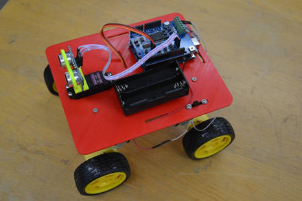
There are three major groups of components. These include the mechanical parts, drive train and electronic components.
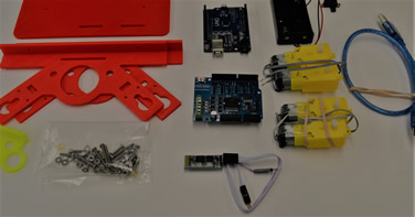
The mechanical parts include the Rover platform for mounting the electronic control components, batteries, servo, ultrasonic sensor and Bluetooth transceiver.
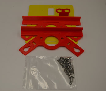
There are 3D printer files (stereographic STL) for each of the printed parts. These include the Rover platform, ultrasonic sensor mount, and right and left motor side plates. Machine screws and elastic nuts are used for assembly.
The battery holder is attached using double-side tape.
The Drive Train Components
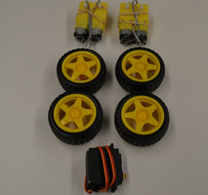
The Rover drive train consists of four gear motor drives with individual wheels. The wheels are pushed on and are a “light” friction fit. The servo is mounted using four plastic spacers and socket head machine screws.
The Electronics and Battery Supply
The electronics components are Arduino UNO board, DC Motor Shield board, Ultrasound Module, Bluetooth Module, Lithium Batteries & Holders & Power Switch, USB Cable, and Wires

There are three 3D STL printer files required to print the chassis parts. These files are:
- Platform (Filename: rover-platform-servo.stl)
- Two Motor Side Plates (Filename: rover-quad-motor-plate-rev-mm.stl)
- Ultrasonic Sensor Mount (Filename: HC05-tinkercad-ok.stl)
Click on the links above to download the files. Alternatively the 3_D files may be accessed via http://Tinkercad.com
There are five Arduino files associated with the Rover project. These files include:
Preparing the 3D Printer
The Rover Summer Workshop used the Robo R1 3D printer for printing all Rover chassis parts and sensor mount. Tests on both ABS and PLA were made to select the most appropriate material. It was found that the PLA (requires lower temperature) material performed best with the ROBO R1 printer. The physical properties of ABS and PLA proved to be acceptable for all of the printed parts.
It is important to follow the manufacturer recommendations on preparing the 3D printer for printing to avoid delays and errors.
The Robo R1 employs a heated bed that must be coated with a base adhesive material before beginning a printing project. A glue stick is the preferred material. It was also found that the printer bed did require cleaning and recoating of the glue-stick adhesive occasionally. Extrusion temperatures and flow rates affect the quality of the printed product and vary according to the material type. The printer bed temperature must be appropriately set.
There are number of different brands of low to moderate cost 3D printers. The workshop project incorporated several Robo R1 3D printers to produce the printed parts. The printer bed is coated with a glue stick with a thin uniform adhesive layer. An effective coating provides good adhesion for the printed part and minimizes curling of large area parts.
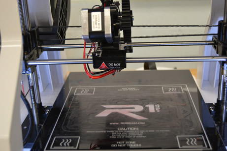
Either ABS (Acrylonitrile Butadiene Styrene) or PLA (PolyLatic Acid) may be used for the Rover project. The filament is inserted and installed in the printer according to printer instructions. It is important to observe the temperature settings and extrusion rates for the material selected.
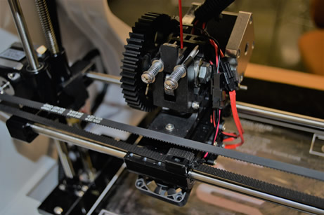
The stereolithographic (stl) files were placed on an SD memory card for convenience and to eliminate “printer time-outs.”
The 3D printing process is very slow on large items such as at Rover chassis and generally cannot be accomplished in a typical single classroom period. The sensor mount and motor mounting plates did not require a large block of time.

Assembling the Rover Chassis
After all of the 3D printed components have been made and ready for assembly, it may be necessary to “clean” the 3mm holes using a 3mm or 1/8” drill to provide easy assembly.
The motor side plates are attached to the Rover platform using two 1/2” 4-40 philips head machine screws, flat washers and elastic locking nuts.
Orient the motor side plate with the mounting flange toward the center of the Rover platform.
Tighten the nuts securely but do not over-tighten the machine screws as it may crush the printed parts.

Assemble the second motor side plate as accomplished previously. Note which side the mounting flange is oriented. Assemble this motor side plate with the mounting flange toward the center of the Rover platform.
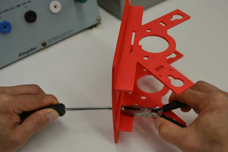
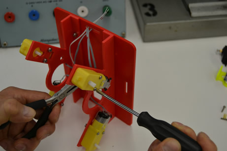
Attach gear motor drives to Rover side plate using 4-40 X 1-1/4” machine screws washers and elastic lock nuts. The motors should be mounted with the wire-side out. Place washers and nuts on the inside of the motor side plates.
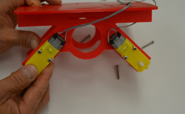
Attach the last pair of motor units to the other side plate. Note that the motors are wired together. Each pair of motors are connected together to turn in the same direction. When the motors are properly connected, all four motors will turn in the same direction in a forward or reverse mode.
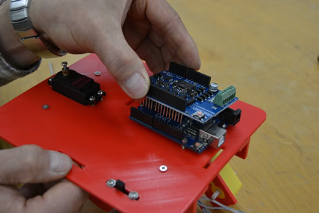
Attach the Arduino UNO controller board using three 4-40 X 1/2” socket head machine screws with plastic spacers, washers and nuts. Do not over-tighten screws. The programming USB “B” socket must face outward (away) from the Rover platform.

Attach the motor shield to the Arduino UNO board. Use care in aligning the shield orientation and connector pins. The screw terminals are oriented toward the silver USB connector on the UNO. The shield pins will not “seat” all the way into the UNO connector sockets.
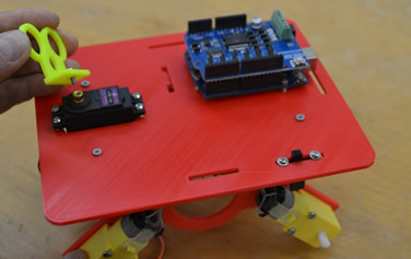
The sensor mount is attached to the servo shaft with a single screw and washer. Insert the screw into the sensor mount and attach to the servo. Do not over-tighten the screw. The servo mount may need to be adjusted during testing to the Rover. The sensor mount should be in the center position of the servo travel.
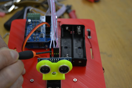
The ultrasonic sensor is inserted into the sensor mount. It should fit snugly. A notebook paper shim may need to be wrapped around the sensors to hold them in place. The connector pins should point upwards as shown.should be in the center position of the servo travel.
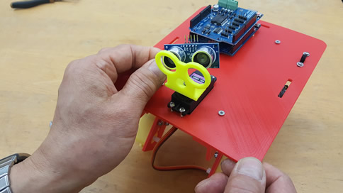
Attach the sensor cable to the ultrasonic sensor. The single wire shown at the left is the ground wire. The wire on the right side is the positive power wire. These wires must be connected correctly or the sensor will be damaged! The Echo pin is connected to A4 and Trigger is connected to A5. Caution!
The motor wires are connected in pairs with red-band wires connected to the A+ and B+ terminals on the motor control board.
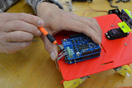
Use care in tightening the screws. Do not over tighten!

Connect the battery and power wire harness to the power switch. The connectors will plug in to each other. Caution!
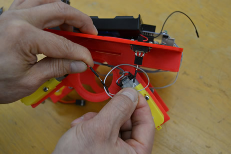
Check to see that the connections are made correctly. Note the positions of the wire connectors. Caution!

Connect the positive switch wire to the Vin terminal. Caution!

Note that the wire coming from the switch must be connected to the Vin (positive) terminal on the motor board as shown. The negative wire is connected to the GND terminal on the motor board. Caution!

The shafts on the Rover motor gear boxes have “flats” on the shaft. The flats on the shaft must be aligned correctly so that the wheels will slip on the shafts snugly. Hold the yellow motor gear box securely when attaching the wheel.
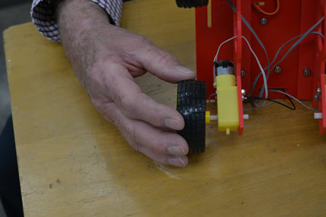
Attach the remaining three wheels.
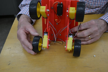
The Rover assembly is complete. Perform the following checks.
- Chassis assembled
- Arduino installed
- Motor Shield installed
- Power switch installed
- Servo and ultrasonic sensor attached
- Servo wires connected to A2 terminals
- Sensor wires attached correctly
- Switch assembly installed
- Switch wiring correct
- Motor wiring correct
- Battery holder attached
- Wheels attached

Connecting and Programming Arduino
Caution! When programming the Rover Arduino board the Rover power switch must be OFF!
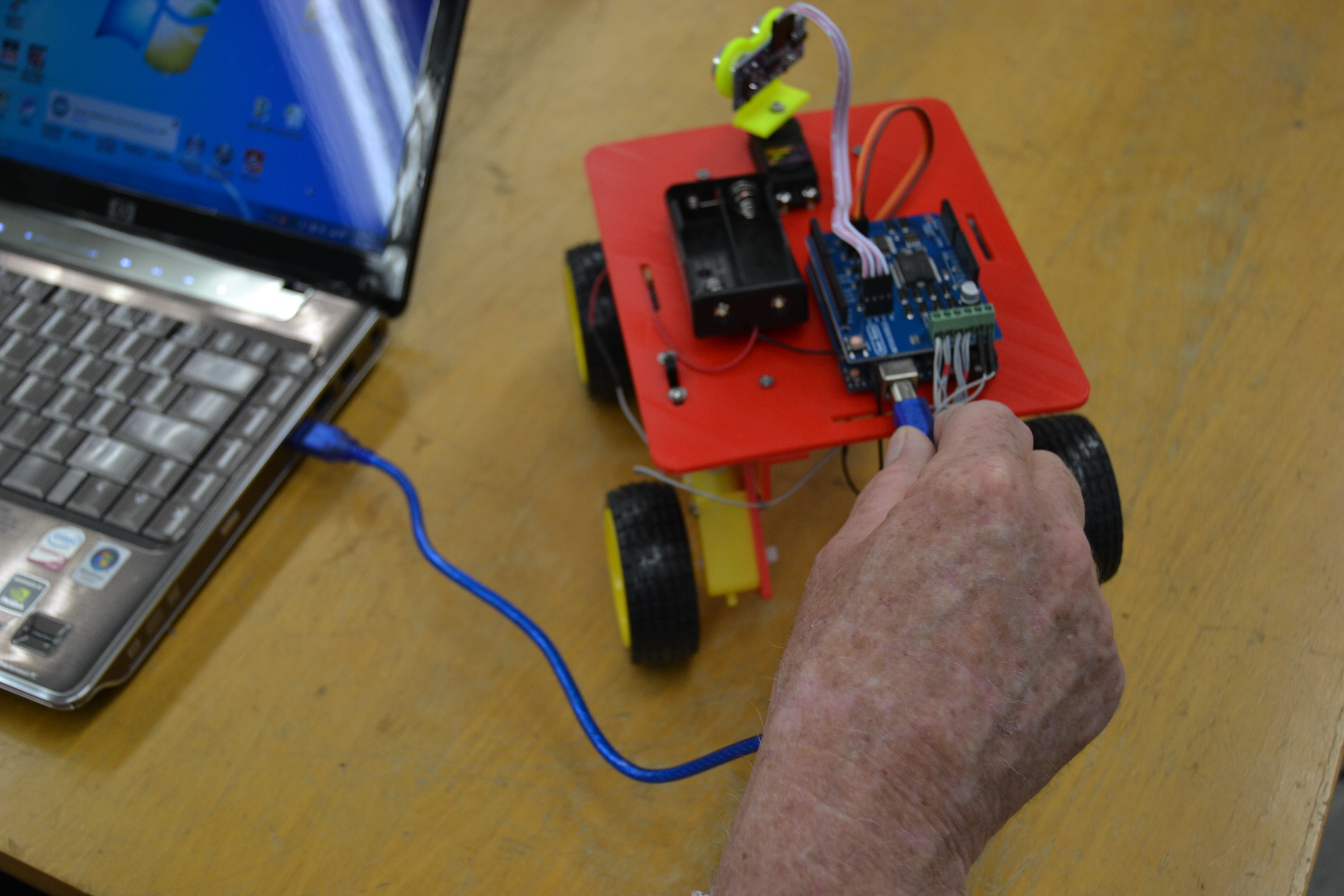
Plug in the Arduino programming cable. A programming cable is used to connect the Rover Arduino to a computer USB port. The computer should automatically recognize the Arduino UNO board.
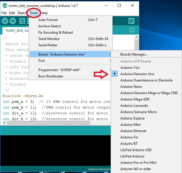
If the Arduino board is not correctly recognized, it will be necessary to select Tools on the menu then select Board. The correct board is Arduino/Genuino UNO.
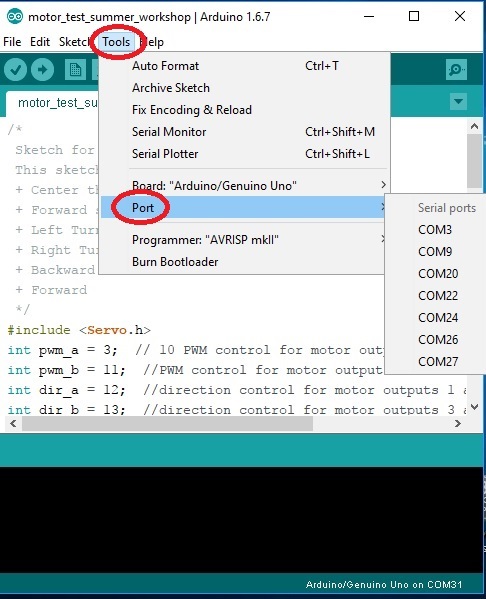
Set the correct COM port. It may be necessary to select the appropriate COM port. The COM port may be selected using selecting Tools on the menu bar. Additionally, it may be necessary to install a special CH341 driver for the Arduino board.
Programming Arduino for the first time. Use the Center Servo and Motor Test program to verify assembly of Arduino Rover. The filename is motor_test_summer_workshop.ino. This program should move and center the ultrasonic sensor servo and run the drive motors forward and backwards. There are comments in program code to describe functions and operation.

With all of the connections to the Arduino and motor shield board on your Rover and batteries installed, your Rover should proceed through the basic servo and motor tests satisfactorily. If not, please check the wiring connections.
Most of the hardware components are connected to a power source. The polarities on the various connectors must be made correctly. Common faults are reversed connections or connection to the wrong board pins. Simple typographical errors will also cause problems.
Autonomous Rover
Autonomous Rover – To operate the Rover in an autonomous mode upload the file named HC05_ultrasonic__summer_workshop.ino to the Arduino UNO board. The autonomous mode requires that the ultrasonic sensor and servo be connected to the Arduino motor shield board.

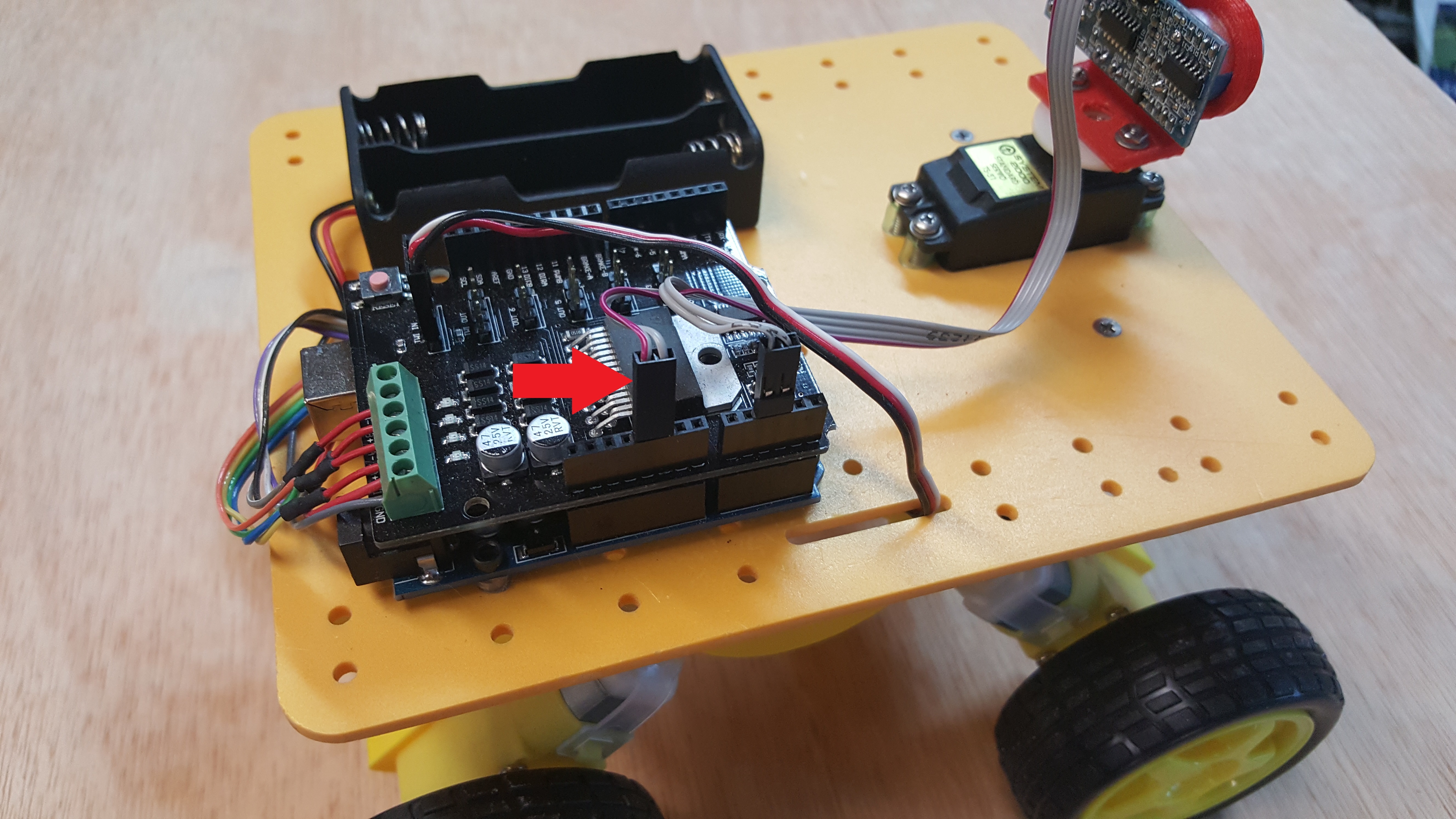
The servo is connected to the Arduino SDA/SCL port on the motor shield. This port may be labeled TWI IN. There are four pins on this port labeled as SCL, SDA, +5, and GND. The servo connector has three wires white wire is Signal, Red wire is +5, and black wire is GND. The white signal wire is connected to SDA, red wire to the +5 volt pin, and the black wire is connected to the GND pin indicated by the arrow shown in the photo. Be sure to orient the servo connector properly. The SDA port is the same as Arduino port (A4).

Make the ultrasonic sensor connections. There are five pins on the ultrasonic sensor. Only four pins are used on the sensor board, These are Vcc, Trig, Echo, and GND.
The pins are labeled on the ultrasonic sensor. Insert the plug connectors on the sensor pins. The echo pin is connected to A2 port and the Trig pin connected to the A3 port on the Arduino board. Caution! Be sure to observe pin connections. Damage can result if not connected properly!
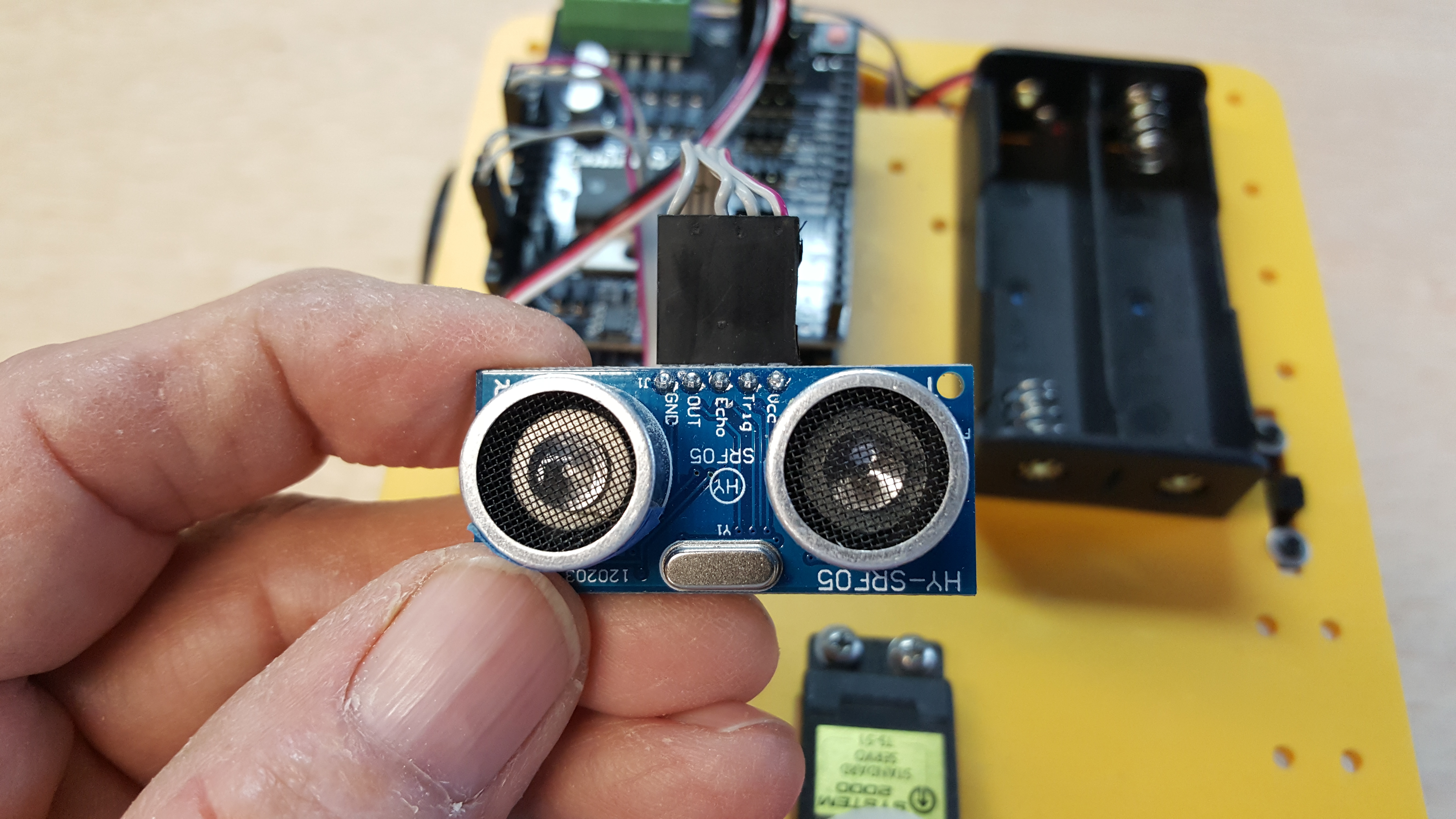
The arrow points to the ultrasonic sensor cable that is connected to the +5 and GND terminals on the Arduino motor shield board. Caution! Be sure to observe pin connections. Damage can result if not connected properly! The echo pin is connected to A2 port and the Trig pin connected to the A3 port.
Bluetooth Rover
Bluetooth Rover – The Rover can be operated using the Bluetooth transceiver module for remote control operation using a smart phone and Arduino control app.. Connect the Bluetooth module using the 4-lead cable. Caution! Connect the +5 volt wire from the Arduino to the Vcc terminal on the transceiver. Connect the GND wire to the GND terminal. The Arduino Rx is connected to the TX transceiver and transceiver Tx is connected the Arduino RX.
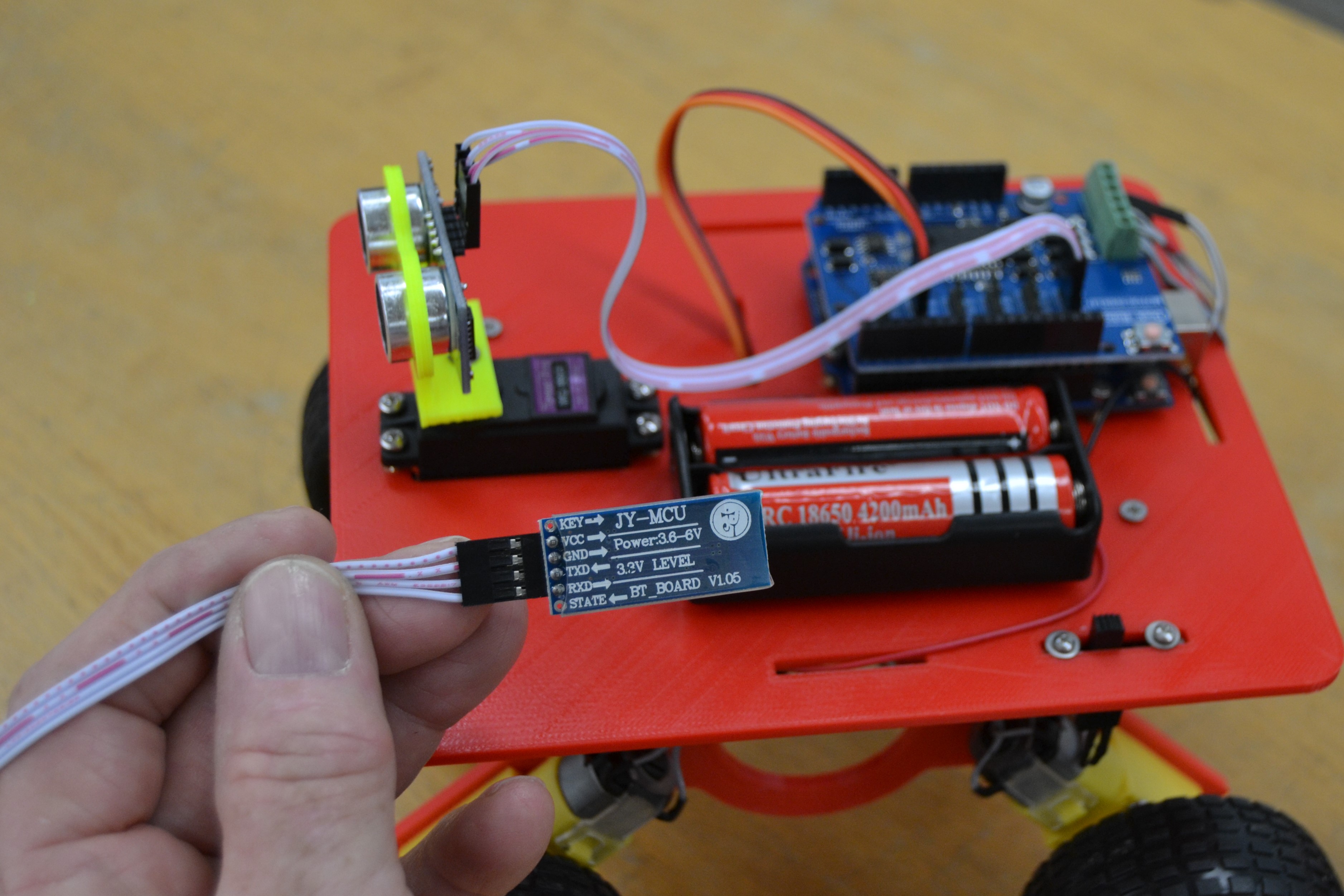
Carefully, place the Bluetooth transceiver module in the slot next to the Arduino board.
Note: The Rx and Tx connector on the motor shield board must be disconnected to enable programming of the Arduino. The Arduino programming IDE will “freeze” if the Rx and Tx are connected to the board while attempting to upload program to the Arduino.
Disconnect the Rx and Tx connector on the motor shield board. Next, connect the programming cable from a PC USB port to the Arduino USB jack. Open and upload the file named bluetooth_car_9600_pwm_workshop.ino.
Caution! Allow the program code to compile and upload to the Arduino. The uploading progress can be seen at the bottom of the IDE programming screen.
After the program has been uploaded, disconnect the USB programming cable from the Rover and plug in the Rx and Tx connectors on the motor shield board.

The smart phone Bluetooth Robot Control App (Bluetooth Robo Control) may need to be installed on your smart phone to control the Rover.
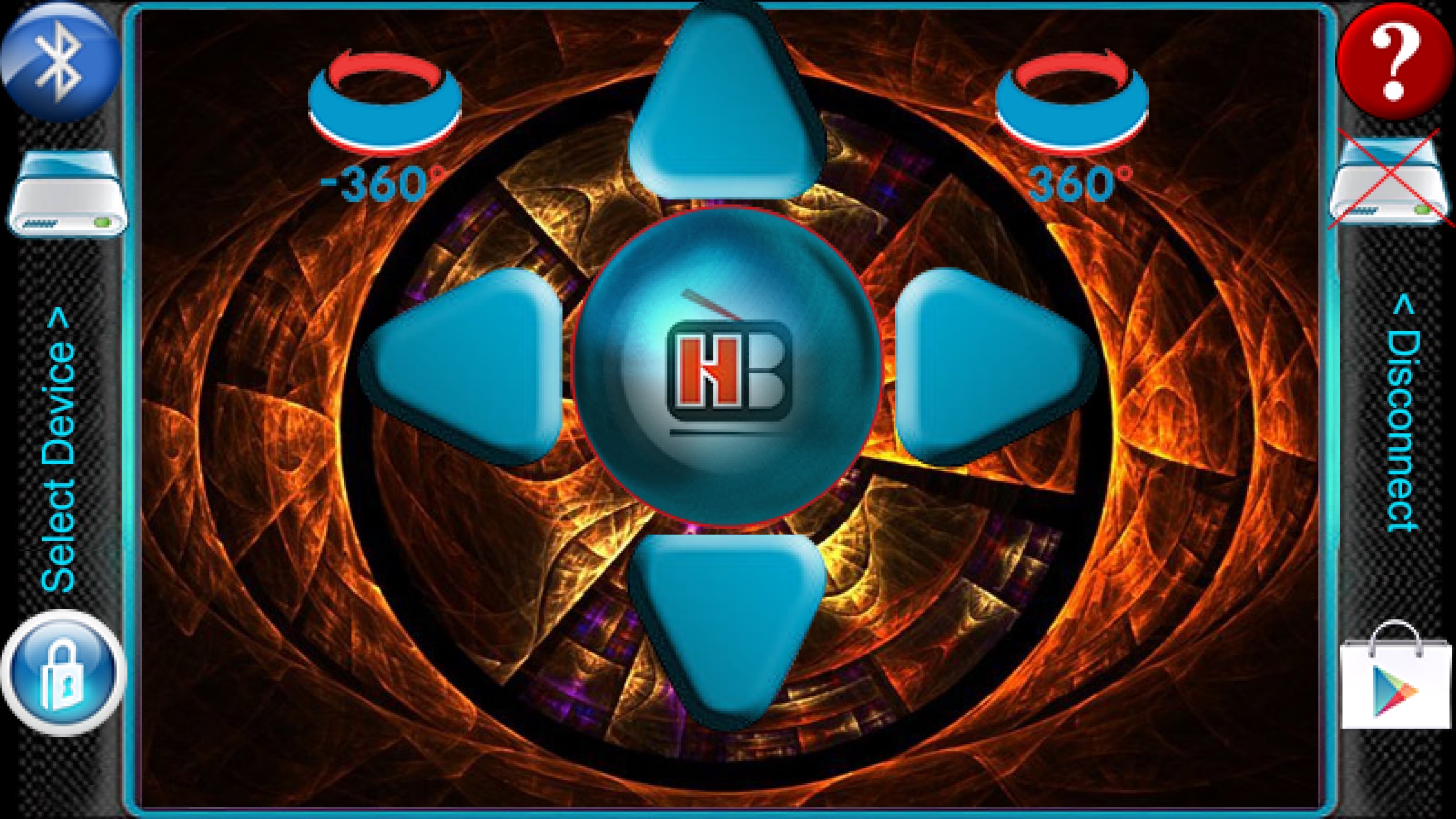
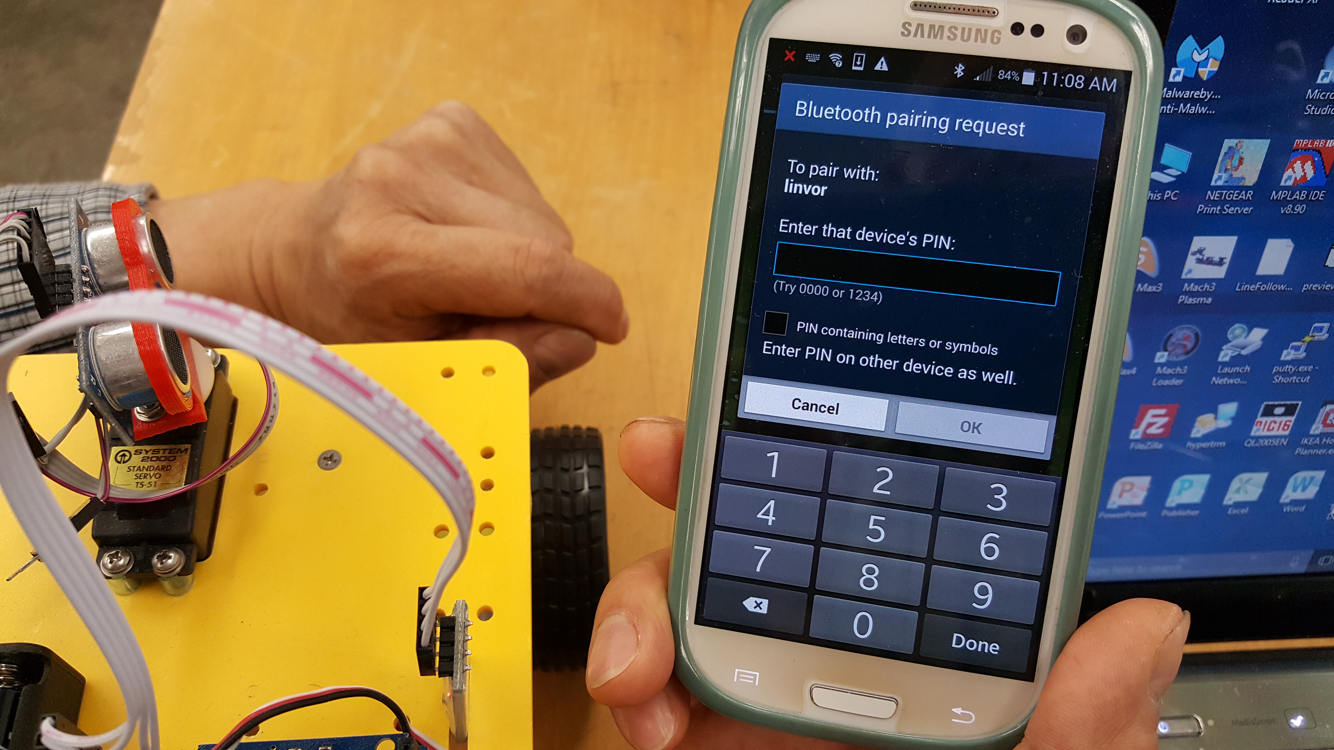
Turn the Rover power switch on and run the Bluetooth Robo Control App. It is necessary to “pair” the transceiver and smart phone Bluetooth connection on the first use. The passcode is generally “1234.”
The Bluetooth transceiver and phone must have established a connection to pair. Each BT transceiver has a unique ID. The Red LED indicates the status of the Bluetooth connection. When the LED is flashing, it is waiting for a connection. The transceiver LED will stop flashing and turn red when a connection is made.
The recommended Arduino Bluetooth Remote Control App may be downloaded from Google Play “Bluetooth Robot Remote Control” by HobbyProjects.com.
Alternatively the App may be downloaded directly from this LINK. Once the Rover is “connected” to the Arduino Bluetooth Robot Remote Control App, use the “controller” interface to control the Rover. The arrow key actions are forward, reverse, left and right turn and stop. The keys do not need to be continuously pressed. Two additional keys shown will make the Rover spin 360 degrees to the right or left.
The trial and testing phase begins after the Rover Robot has been programmed for Bluetooth control or autonomous operation. Both of these applications simulate real-world engineering and STEM problems faced by engineers and researchers.

There are sections of the Arduino code for both the autonomous and Bluetooth programs that determine the speed of the Rover. The program uses the “analogWrite” function and a pwm value between 0 and 255 (maximum speed) to set the Rover speed. As the speed of the Rover increases it may become difficult to “drive.” Conversely, if the pwm value is too low the Rover may not have sufficient power to move and navigate.
